
Using Sketches In FreeCAD

The obvious way to design a 3D print project in FreeCAD is to start with a basic shape, then add or subtract other shapes until you get what you want. That’s not the only way to do it, though. You can also use what FreeCAD calls “sketches” to create some very complex shapes – or you can simply import an existing drawing, turn it into a sketch and use that as the basis for your design.
Importing A Drawing
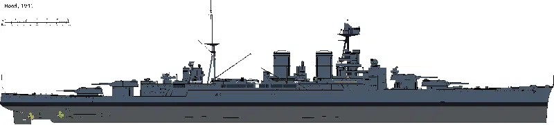
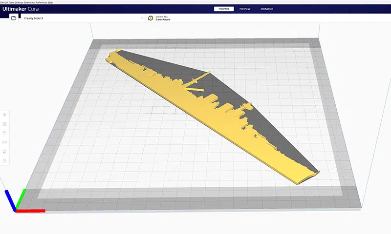
A couple of days ago I decided I needed a silhouette of HMS Hood. I could have created one the way I usually create 3D print objects, but that would have taken hours. Obviously it would be much easier to start with an existing drawing, which in fact I already had. So how do you do this?
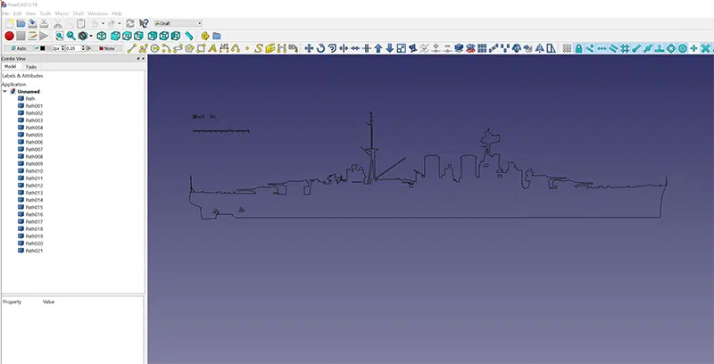
The first step is to turn the drawing into a format FreeCAD can read, which means an SVG file. I did this with an online converter that simply converts the file and downloads it to your PC. Next, open FreeCAD and go to the Drafts workbench; choose Import from the File menu, then find the SVG file and open it. You’ll get a choice of opening it as a drawing or geometry; pick geometry. The SVG will open as a collection of separate “paths” that make up a simplified outline of the drawing.
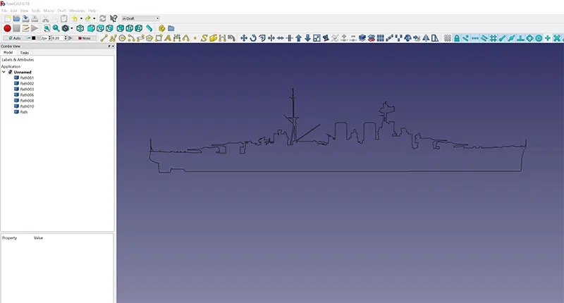
At this stage you can make some tweaks. I deleted a few small elements – like the propellors – that I didn’t want in the final model. Next, select all the remaining paths, open the Draft menu and click Draft to Sketch. This will create a sketch for each of the paths imported in the SVG file. Now go to the Sketcher workbench, select all the sketches, open the Sketch menu and click Merge Sketches. This will create a new sketch out of all the original ones. You can hide or delete all the paths and original sketches now, leaving your final one.
Now go to the Part Design workbench, create a new body and double-click it to make it active. Then select the sketch, go to the Tasks window and click on the Pad tool. You’ll get asked how to handle the selections; go with “Make independent copy”. Your computer will whirr busily for a few seconds, then come up with a menu asking what height of pad you want to create – in other words, how much you want to extrude the shape by. Then it will create a shape inside the outline of the sketch, and extrude it.
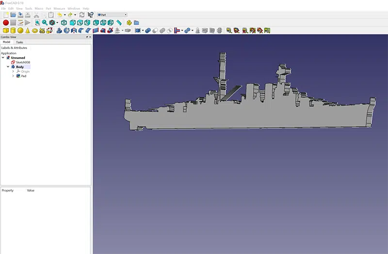
Once your sketch is extruded, it’s just another 3D shape. You can go into the Part workbench and add or remove more shapes, chamfer the edges and all the other things you can do in FreeCAD – including, of course, exporting it as an STL file and loading it into Cura, all ready to print.
OK, But Why?
I was looking for a silhouette of a battleship, so this worked perfectly. I doubt a lot of other people are looking for silhouettes of battleships, though, so is this method actually any use?
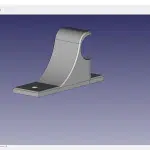
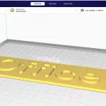
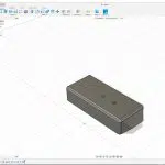
Yes, it is. If you want to print a logo for signs you can either import an image or draw one in the Sketcher workbench. That’s only a small part of what you can do, though – it’s a great way to create parts, too. It takes a little practice to master drawing sketches in FreeCAD, but once you do you can create complex shapes that would be a real struggle to make by adding and cutting the basic ones in the Part workbench. Draw an outline and extrude it to the height you need, then use basic shapes to create any holes or cutouts you need.
There are other options, too. Extrusion is the easiest way to turn an outline into a 3D shape, but you can also rotate an outline around one of its edges – great if you need a shape with a circular cross-section. I’ll explore that in a future article. Meanwhile I have some iron-impregnated filament to play with this weekend, so come back soon!

Leave a comment
You must be logged in to post a comment.