
3D Scanner – Take Two

A few weeks ago I had a shot at building a cheap 3D scanner out of 3D printed parts and my phone. It was a nice idea, but it didn’t quite work. The issue seems to be that the volume control it relies on doesn’t quite fit properly into the printer body, and so far none of my tinkering has found a solution for this. I may have to redesign one of the major components of the scanner body, and as those are all hammered together so tightly they might as well be welded, replacing the original isn’t likely to be easy.
Anyway, I mentioned at the time that I was also looking at a more complex scanner, and I’ve decided to go ahead and try that one. Over the last couple of weeks I’ve been printing parts and gathering electronic components, and I’m just about ready to assemble and test it. This is going to be an interesting challenge, because it does involve some soldering and my soldering skills are limited, to say the least.
Introducing Arduino
The design also involves an Arduino microcontroller board, two motors and some other electronic components. This obviously makes it a lot more technologically sophisticated than the hand-cranked one I already tried. It works on the same basic principle – it’s a photogrammetry device that uses a phone as a camera – but once it’s built the actual operation should be a lot simpler.
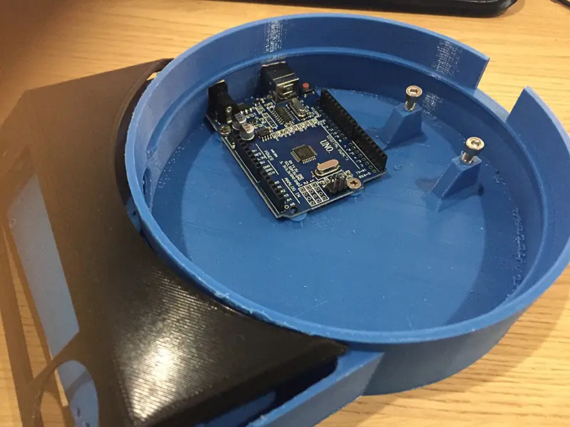
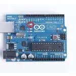
The Arduino, already screwed in place.
At the core of this 3D scanner is the Arduino. This is a circuit board about the same size as a credit card, with power and USB sockets at one end and an array of connectors on top. That lets you power it up, programme it and connect all sorts of components that can then be controlled by its on-board ATmega16U2 microcontroller. Programme code can be written in a simple Arduino-specific language, and there are ready-made ones all over the internet. If you have an Arduino (or a handful of them – compatible clones can be found on Amazon for £10) and know how to programme the thing, you can build some fairly advanced hardware using cheap components and 3D printed parts.
How Does It Work?
In this 3D scanner, the Arduino controls the operation of two motors. One is a stepper motor, a smaller version of the ones that drive a 3D printer. The other is a servo. Between them they carry out the two functions of the scanner – rotating the object, and taking the pictures. The stepper rotates the platform via a geared wheel, which drives a large print-in-place bearing with a geared inner surface. The servo presses the button on a Bluetooth remote paired with the phone, taking a picture with each press.
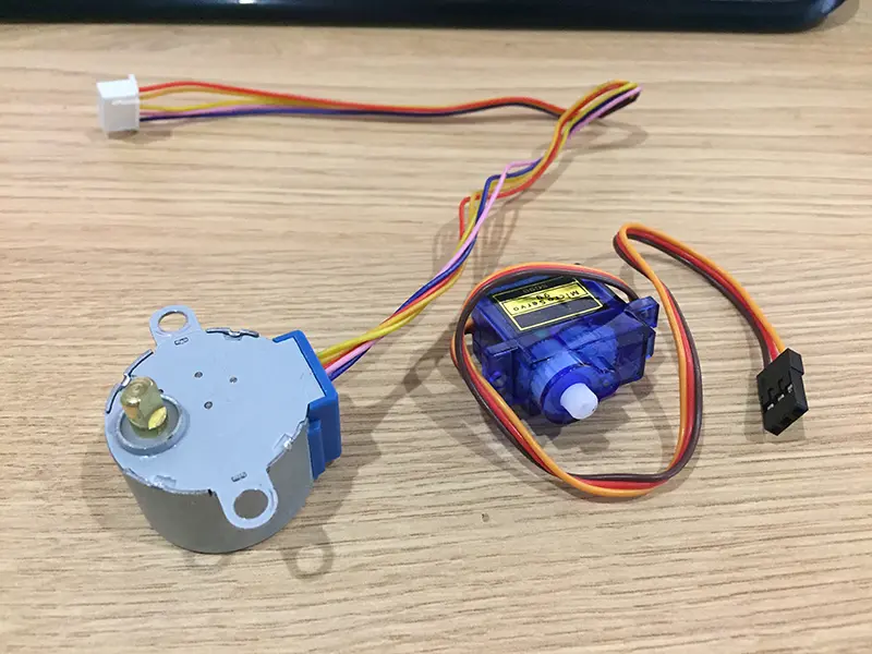
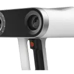
The stepper motor (left) and servo (right).
The job of the Arduino is to control the rotation speed of the platform, and let you select how many pictures to take in a full revolution. The front panel has an LED screen, which together with a small joystick and a potentiometer lets you adjust the settings. It can rotate at between one and 17rpm, and the camera can be set to take up to 200 photos per revolution – a lot more than my photogrammetry software can handle.
I got most of the components from an Arduino starter kit I bought a few weeks ago, but I checked on eBay and Amazon – they’re all easily available and inexpensive. I’ll give a full parts list in the next article about this project.
So, this will be the most complex 3D print job I’ve done so far, and my first Arduino-based project ever. How will it turn out? Hopefully I’ll have an answer for you by the weekend!


Leave a comment
You must be logged in to post a comment.