Building A Creality Ender 3 Kit
A few days ago I said I was about to try building a Creality Ender 3 3D printer from a kit. Well, today you get to find out how it went.
On Sunday, I signed off my blog post sitting in my office with bits of 3D printer laid out on the desk in front of me. I have to admit, it was a bit intimidating. I’d talked to Ender 3 owners and they’d all said it was doable, although all of them mentioned a couple of bits being tricky. Of course they all mentioned different bits, and I wasn’t sure if this was a good sign or not.
What’s In The Box?
I’ve poked around in the Ender 3 box before, but hadn’t unpacked everything. That was the first step, and it put me in a good mood right at the start. The kit comes well packed, with everything nesting snugly in two high-density foam trays. The top tray contains the printer base and two big aluminium extrusions, plus the power supply unit and control panel. Lift this tray out and you’ll find that the PSU and panel actually extend right through it; be careful neither of them fall out.
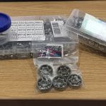
In the bottom tray are lots of bits, including two more extrusions and several bags of smaller parts and tools. I covered the supplied tools on Sunday. They average out at OK, with good Allen keys and terrible spanners, but you can get the job done with them – better than I expected, as it turned out. The screws are all neatly packed in little bags, and clearly labelled with what size they are; there’s no Ikea-style guessing at what goes in what hole.
One observation – the print head comes already connected to the base, but the structure it sits on needs to be assembled, so it’s basically flopping around on the end of a long cable. There are some other dangling cables as well at this stage, and cables can get squished. Be careful when you’re handling the base. You’re going to need to move it around quite a bit, and if you put it down with its substantial aluminium rails on the cables you could damage something. It might be worth taping the cables together and securing them neatly out of the way.
Getting Things Straight
With everything neatly laid out, it was time to get started on building the Creality Ender 3. I’d been warned by one of the videos I’d watched that, as delivered, the print bed can be a bit wobbly on its rails, so the first thing I did was turn the base over to check if the eccentric wheels it runs on needed tightened down. As it happens they were fine, but alarmingly one of the four big adjustment knobs for levelling the bed wasn’t there. A quick search found it hiding in the bottom of the box, though, and it screwed back onto where it was supposed to be easily.
The next step is mounting the two uprights that the print head assembly will run on. These are the bigger pair of aluminium extrusions, and they simply bolt on to the bed. Be careful – they’re not identical. One of them – on the left looking from the front of the printer – has two holes near the bottom to mount the Z axis motor. The other has two different holes to mount the PSU.
It’s vital to get these uprights absolutely vertical, so if you have a set square, use it. Otherwise find something else with a 90° angle, such as the print surface that’s clipped to the bed. Once the uprights are screwed on you can adjust them by tightening the inner or outer screws on each one a little more until they’re vertical.
Fit Some Bits
The next step in the assembly guide is the installation of the PSU and control panel. I mounted the PSU as instructed, but left the panel for now; it looked likely to get in the way. At this stage make sure the PSU is set to the right voltage; there’s a selector switch at the back of it.
Next, fit the Z axis stop switch to the left upright. This is a small L-shaped plastic gadget with two T nuts on the back. Just insert the T nuts into the channel on the upright, slide the unit right down to the bottom, then tighten the screws carefully. The nuts should turn 90° and lock into the channel.
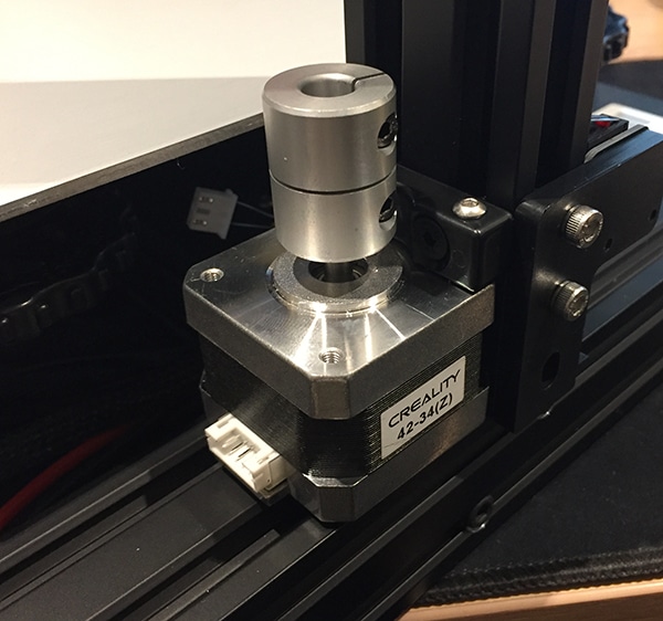
Now fit the Z axis motor to the back of the same upright. It’s held by two screws that go through a bracket at the top and into the holes in the upright. Don’t tighten them down just yet; leave some play in them. Then find the threaded drive rod – it’ll be inside a rubber tube – and drop that into the collar on top of the motor. When you’re sure it’s all the way down the collar tighten the locating screw firmly.
Getting Complicated
The next few steps deal with building the actual print head assembly. Before you do this, find the two carriages the print beam rides on. One of these is just a metal plate with three eccentric wheels on it; the other is a larger plate that carries the X axis motor and extruder unit, and also has three eccentric wheels. Slot each carriage onto an upright and make sure it will slide down under its own weight (don’t let them crash into the base!). If they stick, use the appropriate spanner to slightly loosen the eccentric wheels by rotating their axles.
Once the wheels are adjusted mount the motor carriage to one end of the correct extrusion – you can identify it by comparing the holes with the manual. Now get the carriage back on the upright and make sure the extrusion is level and square with the front of the print bed. At this point the threaded drive rod will need to go through its hole in the carriage.
Now slide the print head onto the beam and mount the second carriage to the other end. Feed the X axis drive belt round the motor axle, along the channel on top of the beam and back round; slot the ends into the print head with the metal tabs pointing down. Fit the tensioner into the end of the beam away from the motor, lever it out a little using a screwdriver to get the belt tight, then tighten down the T nuts that hold it to the beam.
Now you can mount the beam on the uprights and tighten the screws that secure the drive rod guide. Turn the collar on the Z axis motor to raise and lower the beam all the way a couple of times. If it moves smoothly, without binding, you can tighten down the screws on the Z axis motor then raise and lower it again as a final check.
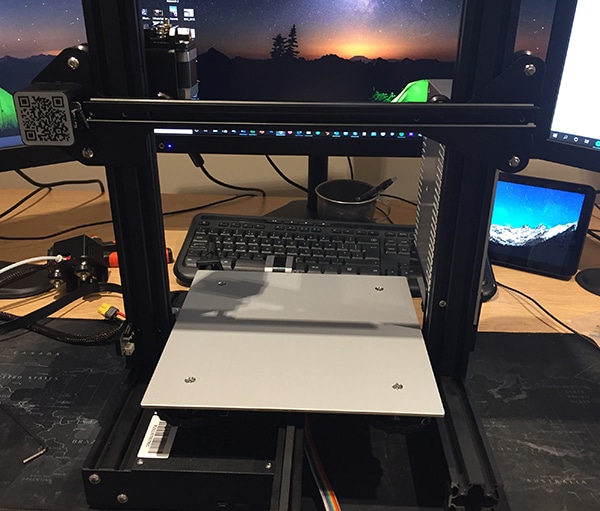
At this stage your collection of bits is now looking a lot like a 3D printer. Complete that impression by mounting the last extrusion as a top bar. If you’ve got the uprights upright, the holes in this should match up neatly – and, to my pleased surprise, mine did. Honestly, though, if the uprights aren’t properly aligned you’d probably have noticed long before now. With the top bar screwed firmly in place, snap on the plastic end caps to make it look tidy and protect your hands from the sharp edges of the extrusion. The assembly guide tells you to mount the filament holder at this point. Don’t; it can wait until last.
If you didn’t mount the control panel earlier (really, it’s easier if you don’t) mount it now, then it’s time to plug all the bits together. All the motor cables are clearly marked with yellow tags marked E (Extruder), X, Y and Z; just plug these into the appropriate motor. There’s a flat one that goes into the third socket on the back of the control panel, and the two halves of the yellow power connector – just make sure this connects red to red and black to black. There’s a white Bowden tube tied to the cable from the print head, and this needs connected too. Screw one of the brass couplers into the extruder and push the tube firmly into it until it locks in place. Then use one of the small blue plastic clips to lock the coupler. Finally, use the supplied cable ties to neaten up the wiring. Use the appropriate screws and T nuts to mount the filament holder bracket on the top bar, and screw the spool axle to it. And that’s it – your Ender 3 is assembled!
The Verdict
One minor reason I’ve been talking about building this Creality Ender 3 for several weeks, instead of actually doing it, is that I was secretly dreading it. Yes, I’ve had a lot going on – moving house, family matters and so on – but honestly, I used to break Lego. I’m pretty good at using technology, but apart from PCs I’m rubbish at building it. So could I really build something as complex as a 3D printer?
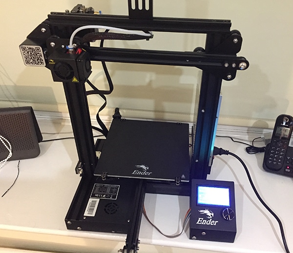
Yes I could – and it was easy. If you can turn an Allen key, and use a square and eyeball to make sure things are properly lined up, you can build a Creality Ender 3 from a kit. What’s more, you can probably do it in an hour and a half, tops. It’s well within the capabilities of the average person. I was very pleasantly surprised at how smoothly this project went.
So, I can build a 3D printer. Next question: Can I build a 3D printer that works? Come back in a few days and I’ll tell you!




Leave a comment
You must be logged in to post a comment.